

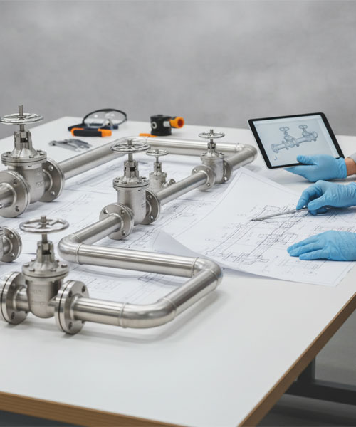
In industrial engineering, the preliminary design of piping systems is a critical phase that determines the safety, efficiency, and economic viability of an entire plant. Piping serves as the “circulatory system” of industrial facilities, transporting fluids, gases, and slurries between various process units. A well-executed preliminary design minimizes future modifications and prevents catastrophic failures.
1. Fundamental Standards and Codes
The backbone of any piping design is adherence to international codes. The most widely recognized standards include:
- ASME B31.3 (Process Piping): The primary standard for refineries and chemical plants.
- ASME B31.1 (Power Piping): Used extensively in power generation facilities.
- API Standards: Often used for specific equipment and piping components.
Following these codes ensures that the material selection, wall thickness, and stress analysis meet rigorous safety margins.
2. Key Stages in Preliminary Piping Design
2.1. P&ID Review (Process & Instrumentation Diagram)
The design process begins with a deep dive into the P&ID. Engineers must understand the fluid properties (viscosity, density, corrosivity), operating pressures, and temperatures. The P&ID provides the logical roadmap for the piping layout.
2.2. Equipment Layout and Plot Plan
Before routing pipes, the physical location of major equipment (pumps, heat exchangers, vessels, and tanks) must be finalized. The “Plot Plan” dictates the available space and the distances between units, which directly affects the length and cost of the piping runs.
2.3. Piping Routing and Line List Development
Once equipment is placed, the routing begins. The goal is to create the shortest, most efficient path while considering:
- Accessibility: Ensuring valves and instruments are reachable for operation and maintenance.
- Safety Distances: Keeping high-temperature lines away from sensitive equipment or personnel walkways.
- Expansion Loops: Providing space for thermal expansion to prevent pipe buckling.
3. Critical Design Considerations
3.1. Stress Analysis and Thermal Expansion
As fluids change temperature, pipes expand and contract. Without proper stress analysis (often using software like CAESAR II), this movement can exert massive forces on equipment nozzles and supports, leading to cracks or leaks.
3.2. Hydraulic Analysis and Pressure Drop
A common mistake in preliminary design is ignoring the pressure drop (ΔP\Delta P) caused by friction within the pipe walls and fittings. Using the Darcy-Weisbach equation:
ΔP=f⋅LD⋅ρv22\Delta P = f \cdot \frac{L}{D} \cdot \frac{\rho v^2}{2}
Engineers must ensure that the delivery pressure at the destination meets the required process specifications.
3.3. Water Hammer and Surge Protection
Sudden changes in flow velocity (e.g., rapid valve closure) can create pressure surges known as “Water Hammer.” Incorporating surge tanks, air valves, or slow-acting actuators is essential during the design phase.
4. Material Selection and Corrosion Management
Material selection is a balance between cost and durability. While carbon steel is common, highly corrosive environments may require stainless steel, duplex alloys, or specialized linings. Understanding the “Corrosion Allowance” is vital for determining the required pipe schedule (wall thickness).
5. Conclusion
Preliminary piping design is much more than simply connecting Point A to Point B. It is a multi-disciplinary effort that integrates process requirements, mechanical integrity, and economic constraints. By strictly adhering to ASME standards and performing rigorous hydraulic and stress analyses, engineers can ensure a robust and reliable industrial piping system.